IN THE UNITED STATES PATENT AND TRADEMARK OFFICE
Utility Patent Application (Provisional)
Lunar Ice Collection System
Marcus van Bavel, Austin Texas
SPECIFICATION
CROSS-REFERENCE TO RELATED APPLICATIONS
Not Applicable
STATEMENT REGARDING FEDERALLY SPONSORED RESEARCH
OR
DEVELOPMENT
Not Applicable
REFERENCE TO SEQUENCE LISTING, A TABLE, OR A
COMPUTER PROGRAM
LISTING COMPACT DISK APPENDIX
Not Applicable
BACKGROUND OF THE INVENTION
The present invention is related generally to systems for extracting
materials from planetary surfaces and using the materials to support
the exploration and settlement of space. More particularly, the
present invention is related to space propulsion, automatic landing
of spacecraft, Lunar ice deposits, vacuum pumping, orbiting fuel
depots, and electrolysis of water for propellant in space.. The
present invention is also related to systems for space solar power,
automated rendezvous and docking of spacecraft, fuel cells, and
automatic assembly of large space structures.
The state of the art for resource mining on planetary surfaces
provides for the landing of a robotic spacecraft on the planet
surface, the scooping and collection of solid materials into a
container on the robotic spacecraft, and launch of the container back
into orbit. However these methods are inefficient and do not generate
more propellant than they use. The present invention provides an
improved and simplified method for collecting volatile materials
including water ice from the Lunar surface using only a dome-shaped
shell, and then brings the water ice to a place where it can be
converted to propellant with Solar energy. The system in its
preferred embodiment produces roughly three times more propellant
than it uses, and can also produce electric power and drinking water.
SUMMARY OF THE INVENTION
The present invention provides a robotic system to collect volatile
materials comprising water ice or other icy materials from a
planetary surface. The preferred embodiment of the invention collects
water ice from the Moon’s permanently shadowed regions.
Accordingly, in this embodiment of the invention, a hydrogen-oxygen
propelled Moon lander is launched with a two-stage rocket into Earth
orbit along with propellant tanks and a stack of lightweight
hexagonal or pentagonal-shaped panels. While in Earth orbit, the
panels assemble themselves into a geodesic dome. Each panel is
equipped with a simple computer guidance system that uses radio
proximity detectors and cold-gas thrusters to position itself in zero
gravity. The panels rendezvous and dock with each other. Magnets on
the edges of the panels grip each other and latching pins driven by
wax motors attach and lock the panels to themselves. Once the dome is
completed into a single large structure of approximately 25 meters in
diameter, the second stage engine of the rocket fires again to place
the lander in low lunar orbit. The lander then descends and lands on
one of the Moon’s polar regions where there is ice on the
surface. In the process of landing and after landing, the lander’s
engine heats up the ice at the surface directly underneath it,
causing the ice to sublimate, and the dome traps the sublimated water
vapor underneath the lander. The exterior of the dome is exposed to
the cold of space and is within the Moon’s shadow, therefore
the temperature of the dome will drop well below the freezing point
of water. Some time after the lander has stopped firing, the water
vapor is allowed to cool and part of it will form ice on the
underside of the dome. On Earth this process is known as cryopumping
where a cold plate cooled with liquid helium is exposed to a
partially evacuated chamber and the remaining air molecules stick to
the plate and a high vacuum (less than 10-4 Torr) is
obtained. Cryopumps are used for particle accelerators, space
environment testing chambers, and other applications where a high
vacuum is needed. In the present invention, the underside of the dome
provides the cold plate and it is cooled by the exposure of its top
surface to space in the absence of sunlight. In another embodiment of
the invention, a liquid helium cooling system actively cools the dome
and radiates the heat through an attached radiator.
In another aspect of the invention, a labyrinth of structures on the
underside surface of the dome provides a large area to collect and
trap the water as it crystallizes back into ice. The labyrinth holds
the ice and prevents it from breaking off when the dome is launched
back into space.
In another aspect of the invention, before re-crystallization some
or all of the trapped water vapor is pumped with a vacuum pump into a
small collection tank positioned over the top of the lander. This
method is useful for measuring the amount of water vapor trapped by
the dome. The collected water vapor is heated by the pumping, and
while it remains a gas inside the collection tank, the mass of the
water can be measured indirectly through the use of the ideal gas law
and knowing the temperature and pressure inside the tank.
In another aspect of the invention, pellets of radioactive material
are used inside the lander to keep the electronics, pumps and
propellant valves warm enough to operate while the lander is
stationed within the Lunar crater and exposed to extreme cold.
In another aspect of the invention, the lander will launch itself
back into orbit and rendezvous with a second lander of similar
design. The two landers will join their domes together to create an
enclosed space where the frozen ice attached to the underside of the
domes can be heated by solar energy, sublimated into water vapor and
collected with a vacuum pump driven by solar electric power.
In another aspect of the invention, the water is transferred to a
fuel depot which has previously been placed into orbit. The fuel
depot collects water from a plurality of landers and stores the water
for later conversion via electrolysis into hydrogen and oxygen
propellant. Part of the produced propellant, about 30%, is pumped
into the lander’s hydrogen and oxygen tanks while it is docked.
This provides the propellant for the lander to return to the Lunar
surface to collect more ice. In the preferred embodiment of the
invention, the landers are reusable and they always collect
significantly more water ice than is used as propellant to land and
take off from the Moon, allowing the system to operate continuously
and always produce more water than it needs to operate.
In another aspect of the invention, the solar panels and radiators
of the fuel depot are self-assembled in Earth orbit using the same
system that assembles the lander domes. In this way all the
components of the system are less than 4 meters in diameter and can
be launched in rockets that have 5 meter diameter fairings.
In another aspect of the invention, the lander dome also serves as a
solar shade for the fuel depot, allowing the hydrogen and oxygen
propellant to be stored for a very long time in orbit with a minimum
of cooling or added insulation. The solar shade is positioned by the
fuel depot’s guidance system to shade the fuel depot’s
propellant storage tanks but without shading the solar array.
In another aspect of the invention, instead of returning to Lunar
orbit, the lander travels from the Moon’s polar region to
another part of the Moon which receives a significant amount of
sunlight. A depot on the surface of the Moon is used instead of one
in orbit. The lander travels by rocket from the permanently shadowed
crater to a position on the Moon that is close to the surface depot.
In this embodiment of the invention, the distance from the landing
zone to the depot is approximately one kilometer. A battery-powered
rover approaches the lander, goes into the interior of the dome
through a doorway, connects a water line to the lander and then pumps
the water vapor from the lander into its own tanks. If there is ice
on the underside of the lander it is allowed to sublimate when heated
with sunlight and then pumped into the rover’s tank. The rover
then carries the water to the fuel depot. This method is used for
water depots that are required for human habitation, or for other
uses on the surface of the Moon. In this embodiment of the invention
enough hydrogen and oxygen is produced during the Lunar day to
provide propellant for the landers. Also in this embodiment of the
invention the depot has fuel cells that can convert stored propellant
into electric power during the Lunar night.
In a further aspect of the invention, the structural parts of the
lunar ice mining system are constructed in zero gravity by
self-assembling geometric panels. Each panel is a flat structure
comprised of carbon composite sheets joined together with a carbon
composite honeycomb or accordion-fold joining the two sides together.
This makes a hollow structural panel that can support 100 times its
own weight, and is thick enough to house the control system and
thrusters for the panel. The panel contains in its interior the
sensors, gas thrusters, and electronic control system necessary to
move the panels through space in zero gravity, rendezvous and dock
with a swarm of other panels, and permanently join the swarm of
panels into a large structure. In this embodiment, the structures to
be assembled are the geodesic domes used to collect the lunar ice,
and the solar panels of the fuel depot. The same assembly system can
also be used to join other components of the system that are launched
separately. Soon after launch but before landing on the Moon, the
panels are released into orbit from the upper stage rocket , and use
their gas thrusters to stay in close formation and assemble together.
Radio proximity sensors on each panel communicate with each other and
measure the distance to each other with 10 cm accuracy to determine
the relative distance and attitude of each panel to each other. Solar
electric cells power the control system. Digital cameras and target
dots painted on the panels allow the panels to rendezvous and dock to
each other with high precision in the final moments of docking.
Permanent magnets draw panels together and locking pins lock the
edges of the panel together and create a high-strength joint. A
two-way digital radio communicates between each panel and the upper
stage of the rocket. The upper stage rocket provides for
communication and monitoring of the assembly process to Earth-based
controllers or to astronauts on a nearby space station. Once the
structure is completed the panels may provide solar electric power,
maneuvering thrust, or radiative cooling to the lunar lander or fuel
depot for orbital or surface-based operations.
BRIEF
DESCRIPTION OF THE DRAWINGS
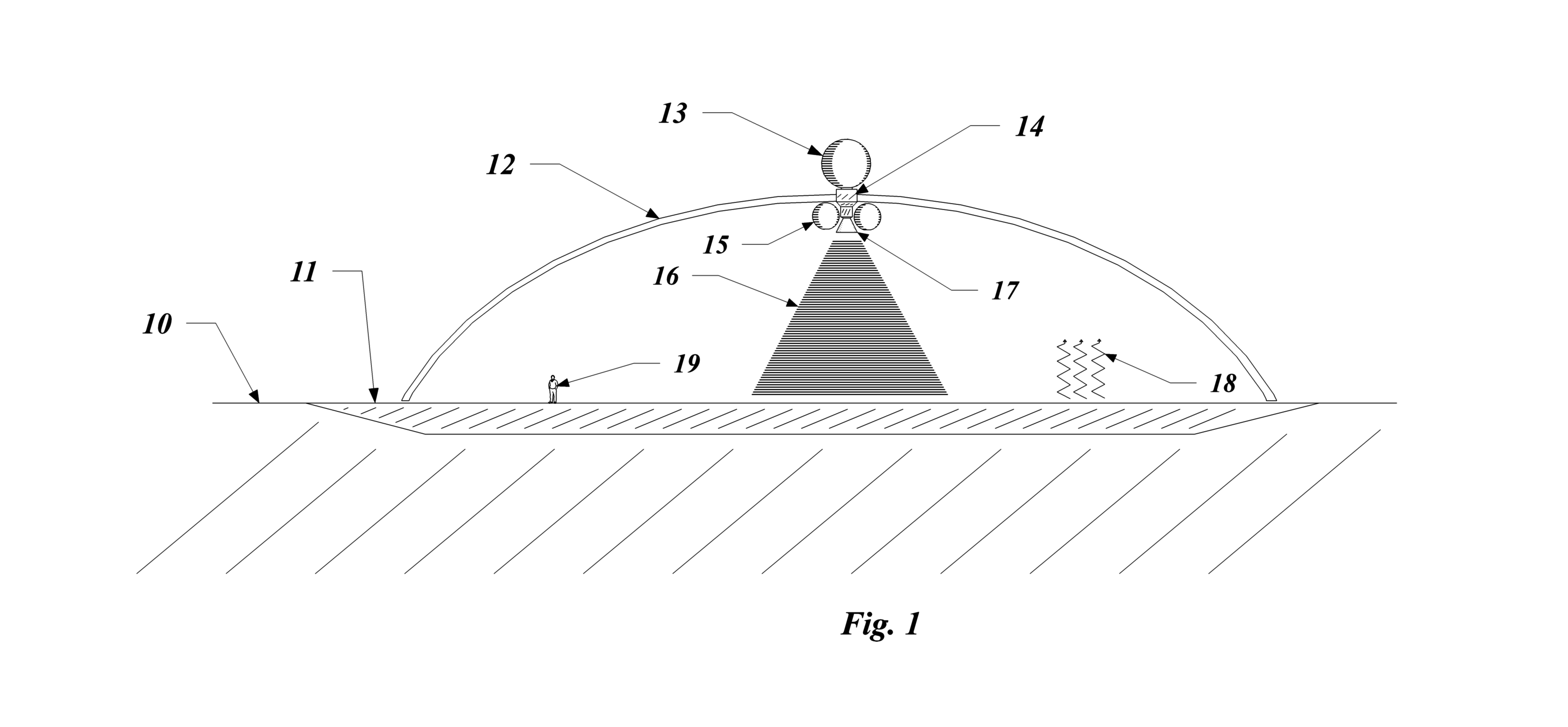
Fig. 1 shows the Lunar lander on the surface of the Moon with the
dome in cross-section.
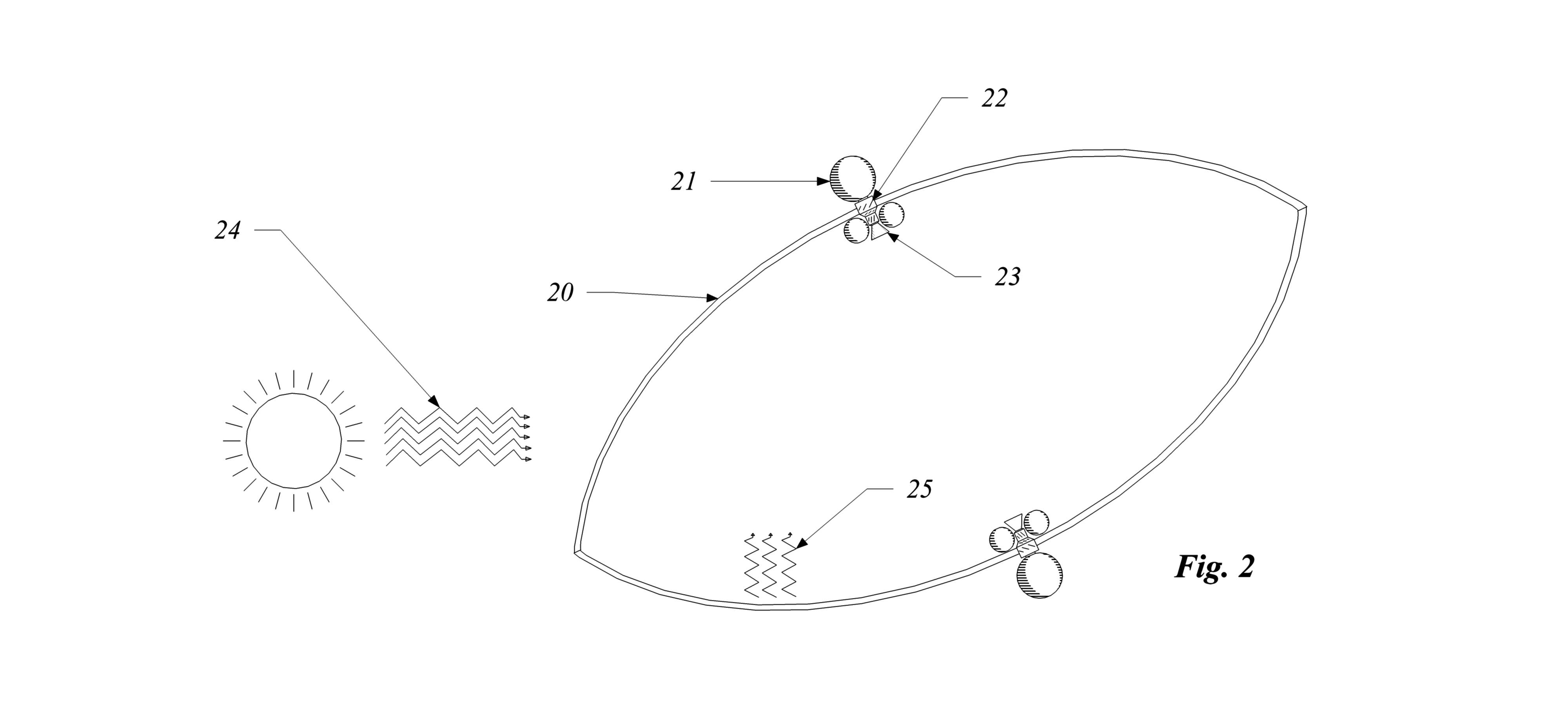
Fig. 2 shows the lander with the dome in cross-section when it is
docked with another lander in low Lunar orbit.
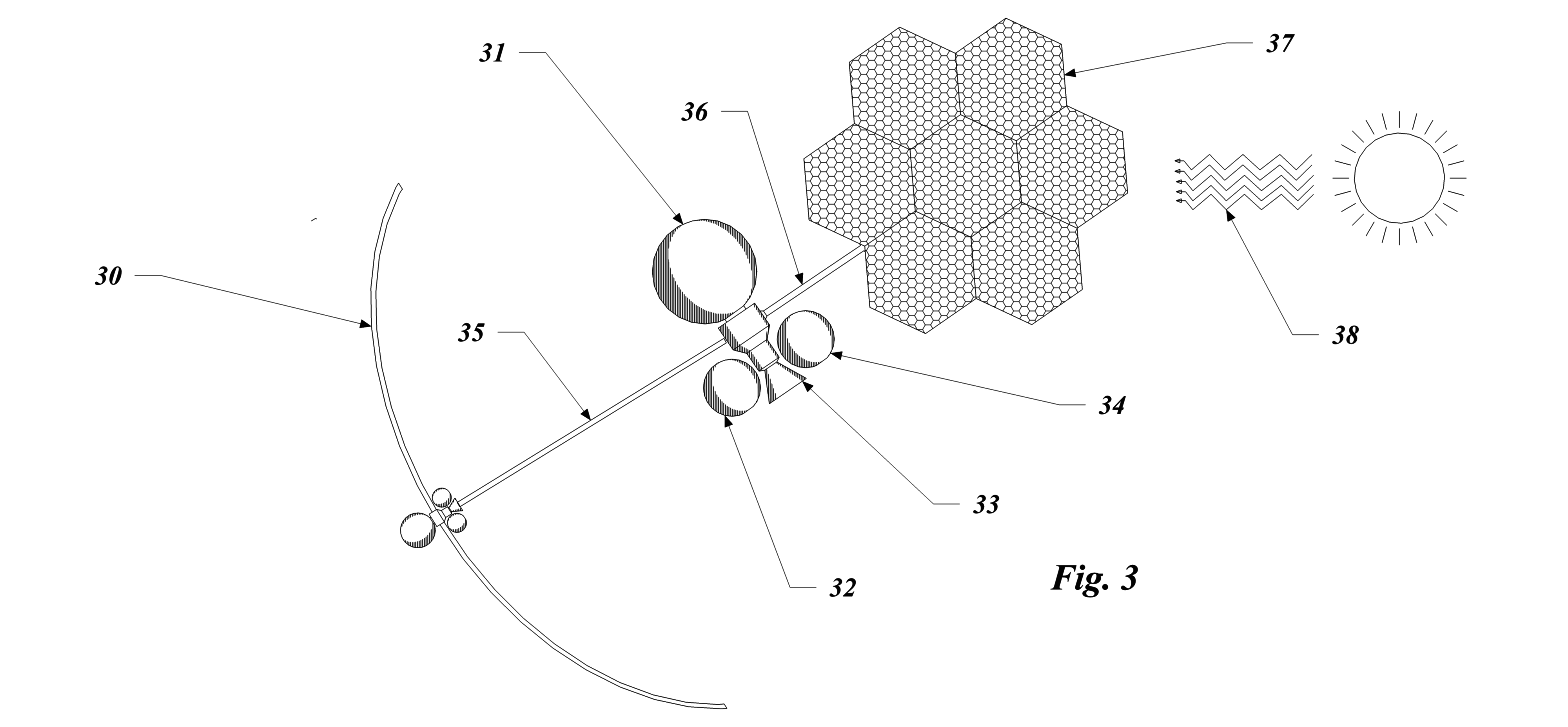
Fig 3 shows the orbiting fuel depot with a docked lander and the
depot storage tanks and solar electric panels.
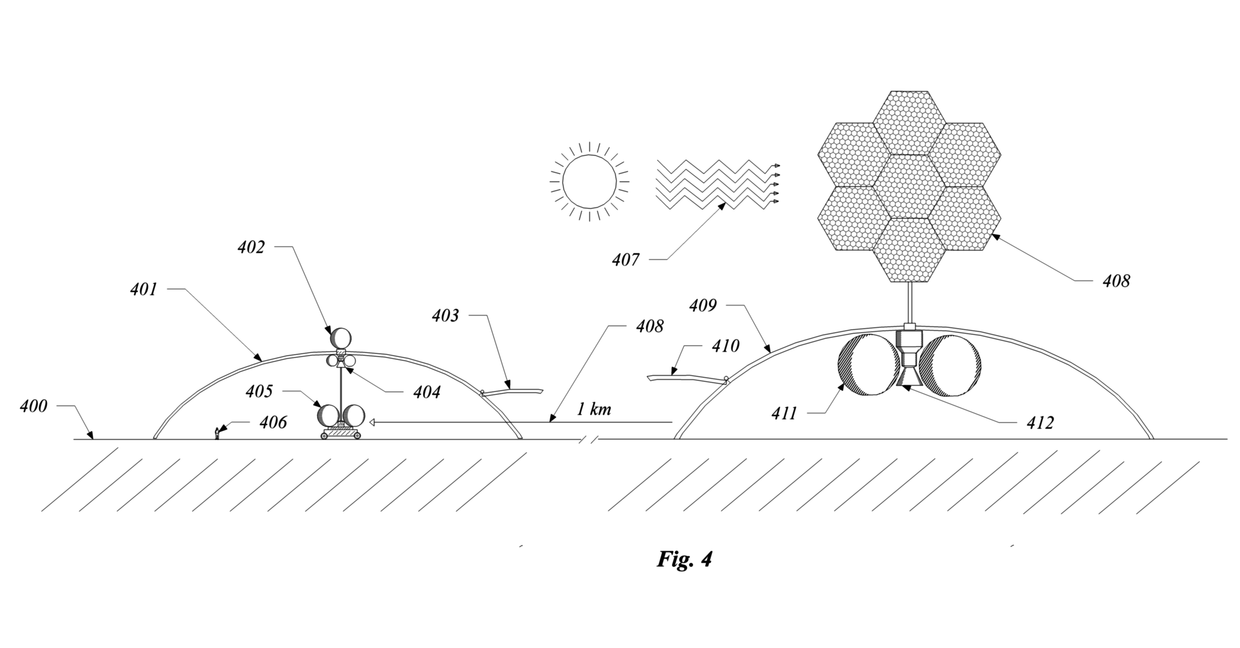
Fig 4 shows the fuel depot on the surface of the moon and a returning
lander.
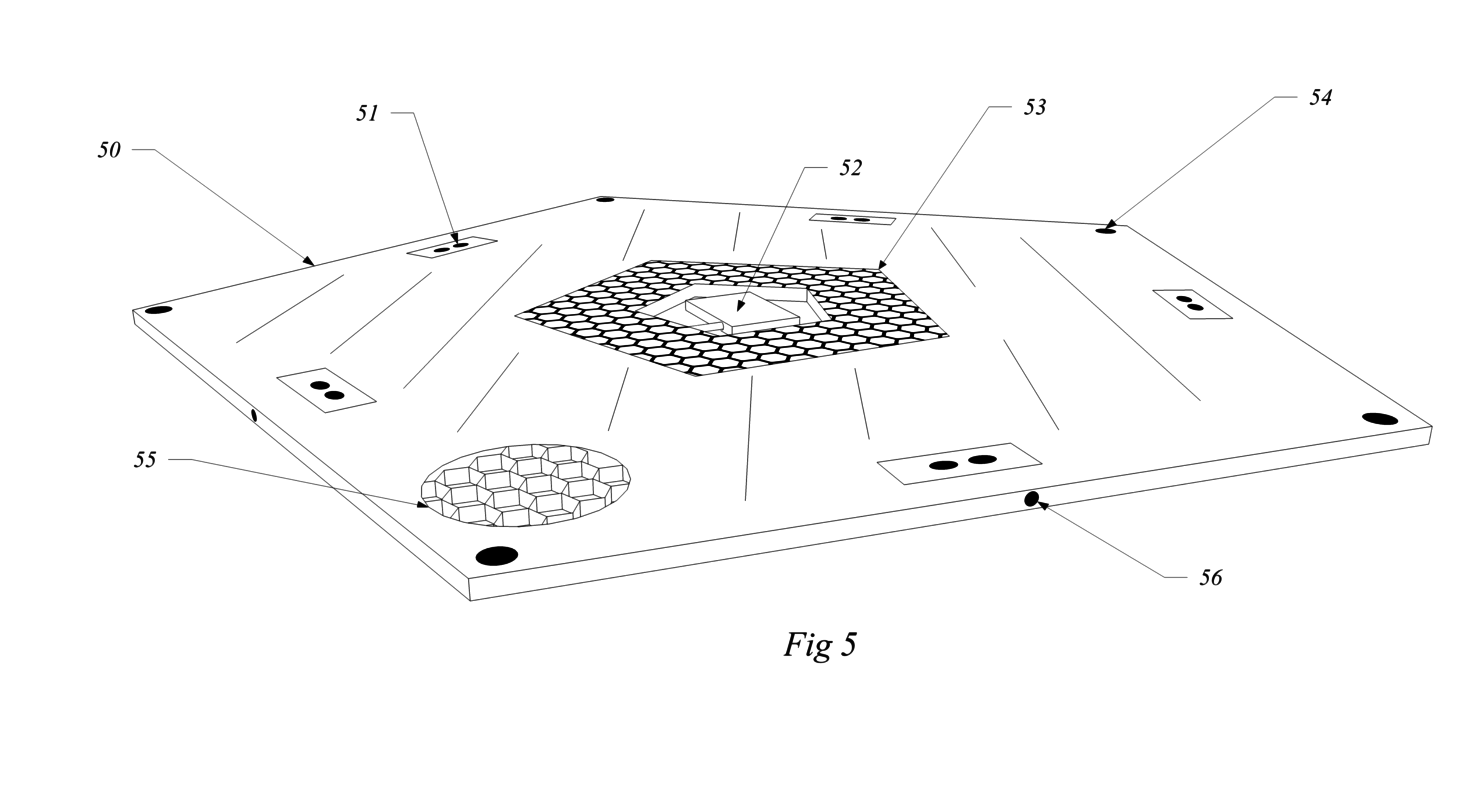
Fig. 5 shows in perspective a lightweight pentagonal structural panel
with solar electric cells, cameras, radio proximity detectors, gas
thrusters and control system.
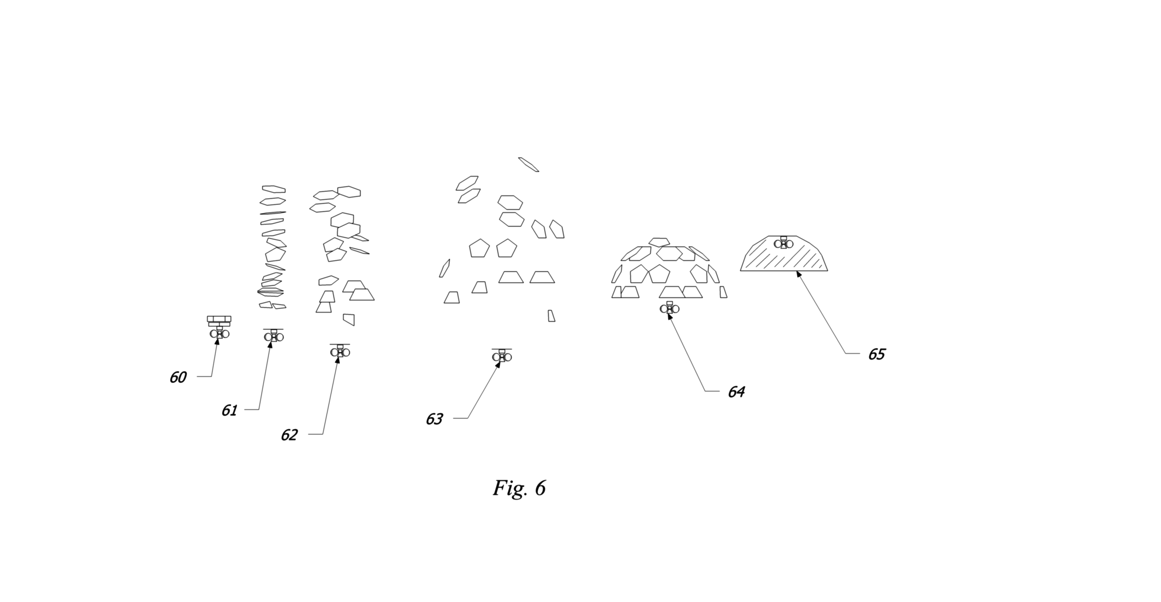
Fig. 6 shows the assembly sequence for a large geodesic dome in low
Earth orbit constructed for later use on the Lunar surface.
DETAILED DESCRIPTION OF THE INVENTION
The present invention will be more completely understood through the
following detailed description which should be read in conjunction
with the attached drawings in which similar reference numbers
indicate similar structures.
In Fig. 1, the invention is used as a Lunar lander. A large,
dome-shaped shell 12 attached to a Lunar lander comprised of rocket
engine 17, propellant tanks 15, water collection tank 13 and control
system 14 lands on the surface of the Moon 10 in the permanently
shadowed regions of the Moon which contain water ice 11 near the
surface. The control system 14 uses ground-looking radar or other
method to choose a flat landing spot free of large rocks and uses the
blast and heat from the rocket engine 17 to clear and smooth out the
surface. For scale a human figure is shown 19, but the system is
entirely automated and no human presence is required.
The heat 16 from the rocket engine 17 impinges on the ice 11, and
causes the ice to sublimate, producing water vapor 18. The water
vapor produced by the heat is pumped through the engine into the
collection tank 13. Or in a further embodiment of the invention, the
water vapor is allowed to form ice on the underside of the dome 12.
In a further embodiment of the invention, the engine repeatedly fires
in short bursts to create enough heat for the ice to sublimate but
not enough to heat the underside of the dome. Radioactive heaters in
the lander 14 keep the lander’s control system warm enough to
operate in the cold environment. In a further embodiment of the
invention, after collecting the water vapor and ice the rocket engine
17 fires again to launch the dome back into Lunar orbit.
In a further embodiment of the invention, the lower edge of the dome
12 is constructed of a soft, conformable material comprised of a
rubbery material or a partially inflated airbag, and coated with a
slick material comprised of teflon or other non-stick plastic
coating. The conformable material improves the seal of the dome
against the surface to prevent air from leaking out. Also flexing of
the material will break off ice that may form and prevent the lander
from taking off. The invention does not require a perfect seal from
outside space, only that the path of water vapor atoms is long enough
to cause a significant number of them to impinge and stick on the
underside of the dome before escaping. In a further embodiment of the
invention, a labyrinth on the underside of the dome 12 is provided to
trap water molecules long enough for them to form ice and prevent the
ice from breaking off when the lander is launched back into orbit.
In Fig 2, the lander 20 is joined in Lunar orbit with a second
lander of similar construction to form an enclosed chamber. Sunlight
24 impinges on the dome and causes the ice inside the dome to
sublimate and form water vapor 25. The water vapor is then pumped
through the engine bell 23 into a collection tank 21 with a vacuum
pump 22. After pumping the water vapor out, the landers separate.
In the preferred embodiment of the invention, each lander joins in
turn with a fuel depot in Lunar orbit or in another part of space, as
shown in Fig. 3. In Fig. 3 the lander 30 is shown docked with the
fuel depot comprised of a large water tank 31, propellants tanks 32
and 34, maneuvering engine 33 and water/propellant transfer line 35.
The fuel depot uses a large solar electric array 37 to collect
sunlight 38 and convert it to electricity. The electric power is
transmitted through a connection line 36 to the depot. The depot uses
electrolysis to separate the water into hydrogen and oxygen gas,
compresses and cools the gas into a liquid, and then pumps the liquid
propellants into the storage tanks 32 and 34 and to the lander 30
while the lander is docked to the depot. After refueling the lander
separates from the depot and returns to the Lunar surface. The
propellant line 35 is then available to fuel visiting spacecraft.
In a further aspect of the invention, in Fig 4., the lander travels
from the icy crater directly to another part of the Moon 400 instead
of going into orbit. In this case the fuel depot is located near a
moonbase or other part of the Moon that receives sunlight during the
Lunar day. The Lunar surface 400 serves as a landing zone for the
Lunar lander 401. The lander arrives with ice from the shadowed
region and has stored the ice in its water tank 402. Any ice formed
on the underside of the domw is alloed to sublimate and it is pumped
into the collection tank. A door provided in the dome 403 opens and
admits a lunar rover 405 that has traveled from the fuel depot 409 to
park under or nearby the lander’s tank 402. Water is pumped
from the collection tank 402 into the rover’s water tanks 405.
The rover then returns to the depot 409. At the depot a door 410 is
provided for the rover to enter the depot’s shell which serves
as a solar shade for the fuel tanks 411. A cooling system uses power
from the solar cells 408 or from a fuel cell to keep the hydrogen and
oxygen propellants in liquid form. Water is pumped from the rover 405
and separated by electrolysis into propellant and pumped into the
propellant tanks 411. Energy from sunlight 407 shines on the solar
electric cells 408 and provides electric power to the depot and to
the Lunar base. During the night, the propellant is used by fuel
cells to produce electric power for the Lunar base and to charge the
lunar rover 405 so the system can operate at night. Enough propellant
is produced to make the system reusable, to continuously supply power
to the Lunar base and produce propellant for the landers to return
and collect more water. Water from the depot can also be used by the
Lunar base and delivered by the rovers either from the depot or
directly from the landers.
In another aspect of the invention the water collection system is
constructed in Earth orbit before transport to the Moon. The
advantage of space-based construction is that smaller rockets and
launch fairings may be used to reduce the overall initial cost of the
system and reduce the amount of resources used to transport the
system to the Moon. Smaller rockets will be reusable and will be
launched more frequently, increasing the reliability of the launch
process and lowering costs. Also extremely large fairings capable of
containing 25 meter wide payloads do not currently exist. Some
construction is space is therefore required and is desirable. The
construction must be fully automated and supervised only at a very
high level by ground controllers or space station astronauts to
reduce operating costs. In this aspect to the invention, a
self-construction method is provided for using smart panels with an
embedded and autonomous control system and low-weight and low-cost
components comprised of solar cells, microprocessors, cameras, radio
sensors, gas thrusters and wax motor actuators.
In this aspect to the invention, one of many pentagonal-shaped smart
panels is shown in perspective view in Fig. 5. In this embodiment of
the invention the panel is comprised of lightweight carbon fiber
composite sheets constructed with a spacing material sandwiched
between them. The entire panel 50 is constructed in one piece using a
3D printer with continuous carbon fiber thread woven throughout the
structure. The carbon fiber composite is capable of supporting 100
times it own weight and can easily withstand launch vibration forces
and support the weight of water ice or lunar regolith on its surface.
Embedded into the panel are gas thrusters 51, control system
electronics revealed in a cutaway view 52, solar electric cells 53,
radio proximity sensors 54, cameras 56, and an interior structural
material revealed in a cutaway view 55. Once transported into Earth
orbit the panel will coordinate with other similar panels, rendezvous
and dock its edges against the edges of other panels, and lock
together with magnets and actuator pins to create a high-strength
joint. The geodesic pattern of construction will evenly distribute
loads throughout the assembled panels and create a very high strength
dome, hexagonal solar panel, or other-shaped structure, capable of
being landed on the Moon intact and relaunched many times. Once its
useful life as a Lunar ice collection system is over, the structure
can be reused as a shelter by or storage building on the Moon by
pushing Lunar dust or regolith on top of it.
Turning to Fig 6. the preferred embodiment of the invention is used
to assemble a geodesic dome in zero gravity. The lunar lander 60 and
stacks of flat panels similar to that illustrated in Fig 5 are
launched into Earth orbit. The stacks separate 61 using the gas
thrusters 51. The control system 52 directs the panels into the
proper order for assembly 62. The panels are then directed to their
approximate positions to attach themselves together 63 and 64. The
fully assembled dome with the lunar lander attached is shown in a
cutaway view 65.
In another aspect of the invention, the landers and depots of the
Lunar ice collection system may be used on the surface of Mars or
other planetary surface with an atmosphere. Turning back to Figure 1,
in the case of Mars, the lander dome 12 also serves a function as an
aeroshell used to brake the lander by friction with the Mars
atmosphere, and to reduce the amount of propellant required to land
it safely on the planet surface. Also the application of the
invention to Mars will require a small rover to scrape the soil off
to reveal the layer of ice 11 underneath the surface or to drill
holes to the ice layer, and to push soil against the interior edge of
the dome 12 to seal it off. Also in the application of the invention
to Mars the lander dome 12 includes windows to allow the sun’s
rays to pass through the dome and directly heat up the ice 11.
In another aspect to the invention the system may be modified to be
used with small asteroids. For an asteroid, a large shell similar to
Fig. 2 is constructed in zero gravity from a swarm of smart panels
(Fig 5) to completely enclose the object in its original orbit. Small
robots are deployed to break up the material so that the volatile
components can be exposed to the interior of the shell 20 and heated
by the sun’s rays 24. A concentrating mirror or lens may be
required if the object is far from the Sun. The sublimated water
vapor is collected with a vacuum pump 22. The rest of the system is
similar to that described for the orbiting depot shown in Fig 3.
While the foregoing written description of the invention enables one
of ordinary skill to make and use what is considered presently to be
the best mode thereof, those of ordinary skill will understand and
appreciate the existence of variations, combinations, and equivalents
of the specific embodiment, method, and examples herein. The
invention should therefore not be limited by the above described
embodiment, method, and examples, but by all embodiments and methods
within the scope and spirit of the invention.
CLAIMS
I claim
1. a system comprising:
a spacecraft with a rocket engine that lands on a planetary surface;
a concave structure attached to said spacecraft for collecting
volatile materials
a heat source to sublimate volatile materials on the surface of the
planetary surface;
one or more of a plurality of methods to trap the volatile materials
in a collection tank or on the underside surface of the concave
structure;
a rocket engine to move the spacecraft back into orbit or to another
part of the planetary surface if that is required;
a fuel depot in orbit or on the planetery surface with means to
transfer the volatile materials to a holding tank and means to
convert the volatile materials into rocket propellant;
a method to assemble the parts of the concave structure in zero
gravityfrom a swarm of structural components, wherein each structural
component has means to control its position and attitude in space,
means to sense position of the other structural components, and means
to attach itself to other components to form the concave structure.
2. The system of claim 1 wherein the concave structure is a geodesic
dome.
ABSTRACT
A robotic system of spacecraft serves to collect volatile materials
from a planetary surface and convert the materials to useful forms
including water, propellant, and fuel for electric power. In the
preferred embodiment, the system is used to collect water ice from
the Moon where permanently shadowed areas have large deposits of
water ice directly on the surface. A large dome-shaped shell is
landed on the ice deposit and the Moon lander engine is used to heat
up the ice and allow it to sublimate. The sublimated water vapor is
then allowed to cool and re-form ice on the underside of the surface
of the dome. Water vapor is pumped into a collection tank. The water
is then used either at the Lunar surface or the water is brought up
to Lunar orbit where solar energy is used to convert the ice into
hydrogen-oxygen rocket propellant for visiting space vehicles.
Because the landers are reusable and efficient, the system produces
approximately three times more propellant than it needs for the
landers to descend and take off from the Moon. The large domes used
to collect the ice are constructed in zero gravity from smart panels
that use proximity sensors, cameras, actuators, and gas thrusters to
assemble themselves from a swarm in space before landing on the Moon.
The system can also be used, with modifications, on Mars or with
asteroids.


